The Heartbeat of the Transmission
In our last blog post we talked about how the solenoid, hydraulic interaction achieves a specific gear and diagnostic tips. We also started off with how the pump is the heartbeat of the transmission. Look inside to read the continuation of this post and its valuable contents inside.
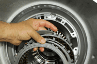
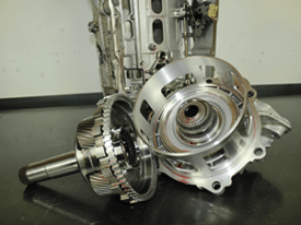
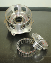
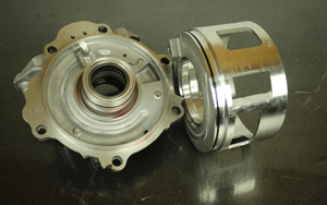
| The 1-2-3-4-5-Reverse clutch pack happens to be the last set of clutches inside the transmission. The application and release of this clutch pack is controlled by an apply piston and a clutch piston dam. These two pistons are mounted in a case extension as seen in Figure 8. Figure 9 shows the clutch piston dam assembly out of the case extension. This piston has three rubber D-rings to inspect. Figure 10 shows the clutch apply piston off of the case extension. This clutch apply piston has two rubber D-rings to inspect; one on the piston and one on the case extension. |
| The clutch piston dam is always supplied with minimum pre-fill pressure G.M. calls the 1-2-3-4-5 Clutch Knockdown pressure. When the 1-2-3-4-5-Reverse clutch is not being applied with line pressure, it too is supplied with the same minimum pre-fill pressure. The rubber D-rings for both of these pistons is constantly sealing pressure as is with all the other pistons in this transmission for the same reasons. For obvious reasons, these seals cannot be compromised in any way otherwise shift quality will be affected. |
Using the above as an example, similar diagnostics steps would be taken for the other three solenoids that are fed with line pressure.
- S7 (A): Torque Converter Clutch with codes P2808 for stuck off and P2809 for stuck on.
- S4 (B): 2-3-4-6-8 Clutch with codes P2714 for stuck off and P2715 for stuck on.
- S3 (C): 1-3-5-6-7 Clutch with codes P0796 for stuck off and P0797 for stuck on.
Each of these solenoids has their own performance characteristic data stored in the TCM. Anytime the transmission, the valve body, solenoids or the TCM has been replaced, a Solenoid Valve Characterization Reprogramming must be performed. Currently, solenoids are not available separately for servicing requiring the purchase of the entire valve body assembly.
The following information about this programming procedure has been provided by GM:
| The solenoids in this transmission require unique performance characteristic data in order to function at maximum efficiency. This data is programmed and stored in the vehicle’s TCM. When a transmission assembly, TCM, or solenoids are replaced during service, the performance characteristic data for the solenoids must be retrieved from a web server “cloud” repository and reprogrammed into the TCM.Reprogramming also ensures that the characteristic data relationship is properly matched between the solenoids, valve body, and transmission. Solenoid characterization reprogramming is performed using the TIS2Web Service Programming System (SPS).
Solenoid characterization may also be performed to “refresh” characterization data. To perform solenoid characterization after a transmission component replacement: |
- Document the new Transmission Unique Number (TUN) or Part Unique Number (PUN) as required. The TUN location may be found here: Transmission Identification Information. Since the TUN can be difficult to access when the transmission is installed in the vehicle, ensure you document the TUN prior to installing the transmission in the vehicle.
- Log into TIS2Web/SPS.
- Type the vehicle identification number (VIN).
- Perform the SPS Transmission Control Module programming event.
Another Option
Select “Transmission Control Module -MCVM Operations” to update Solenoid Characterization data only.
- From the “MCVM (Mechanical Characterization and Virtual Matching) Operation Selection” screen, select the applicable service procedure to be performed. You will be prompted to provide the necessary TUN or PUN when replacing a transmission part. At this point, the system will read the VIN from the ECM using the multiple diagnostic interface (MDI) and then retrieve the applicable genealogy data tree from the cloud. This data tree accesses the original characterization data so that it may be updated with the new component information. The system acquires characterization data for the given TUN/PUN via the cloud and updates the genealogy tree. The TCM is updated with the correct solenoid characterization data, and the cloud is updated with the new genealogy relationship.
Below Is A Basic Diagnostic Code List for the 8L90 Transmission
Basic Diagnostic Code List for the 8L90 Transmission:
- DTC P0601- P0604, P0606, P062F, P16F3, P16F4, or P16FB: Control Module Memory
- DTC P0658 or P0659: Actuator High Control Circuit Group 1
- DTC P0711- P0713: Transmission Fluid Temperature Sensor
- DTC P0716, P0717, P07BF, or P07CO: Input Speed Sensor
- DTC P071A: Transmission Tow Mode Switch
- DTC P0722, P0723, P077C, or P077D: Output Speed Sensor
- DTC P0746 or P0747: Transmission Control Solenoid Valve 1 Stuck
- DTC P0776 or P0777: Transmission Control Solenoid Valve 2
- DTC P0796 or P0797: Transmission Control Solenoid Valve 3 Stuck
- DTC P0815, P0816, or P0826: Upshift/Downshift Switch
- DTC P0851: Park/Neutral Position Switch
- DTC P0960, P0962, or P0963: Transmission Control Solenoid Valve 1
- DTC P0964, P0966, or P0967: Transmission Control Solenoid Valve 2
- DTC P0968, P0970, or P0971: Transmission Control Solenoid Valve 3
- DTC P175F: Acceleration Sensor Signal Message Counter
- DTC P1761: Up and Down Shift Switch Signal Message Counter
- DTC P176B-P176D: Intermediate Speed Sensor
- DTC P1824, P182D, P18B8, P18BD, or P18C2: Internal Mode Switch P Circuit
- DTC P182A, P1838, P18B5, P18BA, or P18BF: Internal Mode Switch A
- DTC P182B, P182C, P18B6, P18BB, or P18CO: Internal Mode Switch B
- DTC P182E or P1915: Internal Mode Switch
- DTC P182F, P1839, P18B7, P18BC, or P18C1: Internal Mode Switch C
- DTC P1840, P1841, P18B9, P18BE, or P18C3: Internal Mode Switch S
- DTC P2670 or P2671: Actuator High Control Circuit Group 2
- DTC P2714 or P2715: Transmission Control Solenoid Valve 4 Stuck
- DTC P2718, P2720, or P2721: Transmission Control Solenoid Valve 4
- DTC P2723 or P2724: Transmission Control Solenoid Valve 5
- DTC P2727, P2729, or P2730: Transmission Control Solenoid Valve 5
- DTC P2736, P2738, or P2739: Transmission Control Solenoid Valve 6
- DTC P27A7-P27AD: Transmission Control Solenoid Valve 1-7
- DTC P2808 or P2809: Torque Converter Clutch (TCC) System Stuck
- DTC P2812, P2814, or P2815: Transmission Control Solenoid Valve 7
- DTC P2817 or P2818: Transmission Control Solenoid Valve 8 Stuck
- DTC P281 D or P281 E: Transmission Control Solenoid Valve 8
- DTC P2824, P2826, or P2827: Transmission Control Solenoid Valve 9
We hope this information has been valuable to you. Make sure to visit our ATSG Bookstore to find more extensive tech manuals, diagnostic guides, CD’s, etc. as well as tools to better prepare yourselves with your customers.


